Beginners Guide to Magic Bit
In this guide we are learning how to use the basic components on the Magic Bit board. The components comes with the Magic Bit is arranged as following. We have provided code examples as well as self assignment set to enhance your knowledge.

Example 1: Blinking an LED
Introduction
In this example you are learning how to turn on and off a LED or any other actuator which can be controlled by a digital output such as relay, bulb, motor.
Learning Outcomes
From this example, you’ll get an understanding about,
- Pin Mode
- Digital Write
- Delay Functions
Components
- Magic Bit
Theory
A digital output allows you to control a voltage with an electronic device. If the device instructs the output to be high, the output will produce a voltage (generally about 5 or 3.3 volts). If the device instructs the output to be low, it is connected to ground and produces no voltage.Here magicbit is the device and output voltage is either 3.3V for HIGH and 0V for LOW.
Methodology
Magicbit equipped with four onboard leds in magicbit development board, Lets select yellow LED (which is wired to D18)

By setting output state to high of LED pin will turn on the led and by setting output state to LOW will turn of LED.
Coding
void setup(){
   pinMode(18,OUTPUT);
}
void loop(){
   digitalWrite(18,HIGH);
   delay(1000);
   digitalWrite(18,LOW);
   delay(1000);
}
Explanation
pinMode(pin, Mode): Configures the specified pin to behave either as an input or an output. Here we use pin as an output
digitalWrite(pin No, State): Write a HIGH or a LOW value to a digital pin.Pin mode must be setup for the same pin in Setup to work this function properly.
delay(ms): Pauses the program for the amount of time (in milliseconds) specified as parameter.(note 1000 milliseconds equals to one second)
Activity
Write code for a knight rider pattern using on board leds of magicbit
Example 2: Reading the state of a push button
Introduction
In this example you are learning how read a digital input from something like a button & use it to turn on and off a LED or any other digital device.
Learning Outcomes
From this example, you’ll get an understanding about,
- Digital Read
- IF-ELSE conditions
- Variables
Components
- Magic Bit
Theory
A digital input allows you to read digital signals. Microcontroller recognizes the signal as 1(HIGH) when the signal is close to 3.3v (or 5v depending on the microcontroller) and recognizes as 0(LOW) when the signal is close to 0v. This reading can be used in the program to do various things.
Methodology
Magicbit equipped with two onboard push buttons in magicbit development board, Lets select the push button which is wired to D34. Buttons on the board are in pulled up internally (to learn more about pullups/pulldowns follow this link), which means when button is not pressed the status of the button is 1(HIGH), & when the button is pressed the status of the button is 0(LOW).

Also like in previous example we need to select an LED to indicate the change, lets select RED LED which is wired to pin D27.
First we set the input output configurations of the Button and the LED using pinMode, in this case button is an INPUT, LED is an OUTPUT. Then in the loop section we check the state of the button & store it in an int type variable called buttonState (follow this link to learn more about data types in arduino).
Then we can use the variable as the condition of the if block, and if the button is pressed, the bulb should turn on, and the button is not pressed the light should turn off.
Coding
void Setup(){
   pinMode(27,OUTPUT);
   pinMode(34,INPUT);
}
void loop(){

 int buttonState = digitalRead(34);
 if(buttonState == LOW){
   digitalWrite(27, HIGH);
 }else{
   digitalWrite(27, LOW);
 }
}
Explanation
digitalRead(pin No): Reads the condition of the given pin and returns a digital value HIGH or LOW.
IF/ELSE: Used to evaluate a digital condition, we can put a digital logic condition in then parenthesis. If the condition is true, it executes the code block in the immediate curly bracket section, if the condition is false it executes the code block in the else curly bracket.
- if(condition){
- //Do if condition is true
- }else{
- //Do if condition is false
}
Activity
Write a code to toggle an LED in the button press. LED turns on when button pressed & released, LED turns off when button is pressed & released again. (Hint: Make use of variables to ‘remember’ the state of the button press).
Example 3: Working with Analog Write
Introduction
In this example you are learning how to turn on and off a LED or any other actuator which can be controlled by a digital output such as relay, bulb, motor.
Learning Outcomes
From this example, you’ll get an understanding about,
- Pulse Width Modulation
- Analog Write
Components
- Magic Bit
Theory
To change the brightness of a LED we could change the voltage the LED is supplied with, but in a microcontroller, ability to change the voltage (converting a digital number to an analog voltage) is limited, so a method called PWM (Pulse Width Modulation) is used. What this does is pulsing on and off the pin in a high frequency. The length of the pulses creates the perception of brightness.
Duty cycle is a term used to describe the ratio between on and off times.
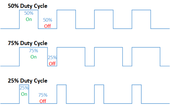
In this example higher Duty cycle gives higher brightness & lower duty cycle gives lower brightness.
Methodology
Lets select green LED (which is wired to D16). We will use a for loop to generate the duty cycle (0 - 0% duty, 255-100% duty). And also to generate 255 cycles.
Coding
#include <ESP32Servo.h>

void setup(){
      pinMode(16,OUTPUT);
}
void loop(){
      for(int i = 0; i < 256; i++){
      analogRead(16, i);
      delay(10);
}
Explanation
for(int i=0; i<256; i++): There are 3 parameters in a for loop, first parameter we are defining a variable to store the value generated by the for loop. Second parameter specifies the condition that needs to be true to run the for loop(else it breaks out from the loop), third parameter specifies the change happens to the variable in each cycle, in this case 1, added to i.
analogWrite(pin number, pwm value): You can input the pin number you need to do pwm and then the pwm value you need to give to that pin. This assigns the corresponding duty cycle to the pin.
Activity
This example we have coded to increase the brightness, write a code to do the opposite of that, to fade the brightness of the led, & put both effects together to create a beautiful fade & light up effect.
Example 4: Using Serial Protocol
Introduction
In this example you are learning to use serial communication function.
Learning Outcomes
From this example, you’ll get an understanding about,
- Serial Protocol usage between Magic Bit & the PC
Components
- Magic Bit
- Computer with arduino installed
Theory
In microcontroller programming, communication between devices is essential. There are hundreds of protocols available, but most common & easy to use is Serial Protocol. Commonly used to communicate information between a microcontroller and a computer.

Methodology
We configure a button as the 2nd example (D34 is used). Then we initialize serial communication between the computer and magic bit. After that in the loop section if condition check if the button is pressed. If pressed, it prints “Button Pressed” on the serial console.
You could use the serial monitor window of arduino IDE to view the serial output

Then the serial console appears (you have to select the serial port number correctly, follow this link to learn how to).

1: You can type in stuff here & hit enter to send data to magic bit
2: This area shows the data coming from magic bit
3: From this menu you have to select a common baudrate between the computer and the magic bit.
Coding
void setup(){
  pinMode(34,INPUT);
  Serial.begin(9600);
}
void loop(){
  if(digitalRead(34) == LOW){
    Serial.println(“Button is Pressed”);
  }
}
Explanation
Serial.begin(baudrate): Initializes a serial connection, baudrate specifies the speed of data transfer (bits per second). Standard values are 1200, 2400, 4800, 9600, 14400, 19200, 38400, 57600, 115200, 128000 and 25600
Serial.print(stuff to print): Using this function, serial data can be sent, stuff to print can be any type of arduino variable, or even a static string.
Serial.println(stuff to print): Using this function, serial data can be sent, stuff to print can be any type of arduino variable, or even a static string, this is different than Serial.print() is this always prints the content in a new line, rather than printing all in one line.
Activity
do the same example using Serial.print(), observe the difference. Create a button press counter, which displays the button press count on the serial console of arduino IDE.
Example 5: Reading an Analog Signal
Introduction
In this example you are learning to read an analog sensor & print it on the serial console.
Components
- Magic Bit
Theory
In real world most of the signals we encounter are analog signals (temperature, air pressure, velocity), they are continuous. But computers work on digital domain, to interact between the worlds, representing an analog signal in the digital domain is important. (to read more about analog to digital conversation, follow this link)
Methodology
For this example we use the potentiometer on the magic bit board, which is connected to pin, D39. It generates a voltage between 0 and 3.3V according to the angle of the potentiometer.

We read the analog signal and storing it in an int type variable(0v= 0 analog value, 3.3v = 1024 analog value), sensorValue, later, we use this value to print on the serial window of arduino IDE as well as light up the red LED(D27) if the analog value exceeds than 512.
Coding
void setup(){
     pinMode(39,INPUT);
     pinMode(27,OUTPUT)
     Serial.begin(9600);
}
void loop(){
     int sensorValue = analogRead(39);
     Serial.println(sensorValue);

     if(sensorValue > 512){
        digitalWrite(27,HIGH);
     }else{
        digitalWrite(27,LOW);
     }
 }
Explanation
analogRead(pin No): this reads and assigns the corresponding analog value to the left.
Activity
Do the same example using the LDR on the board (D36)
Example 6: Generating Tones
Introduction
In this example you are learning to generate a tone using the onboard buzzer on the magicbit.
Components
- Magic Bit
Theory
Piezo buzzers are commonly used in embedded systems to give audible tones. Combined with ESPservo library magic bit can generate various tones. (Follow this link to know how to install ESPservo library)
Methodology
For this example we use the piezo buzzer wired to pin 25 of the Magic Bit.

ESP32Servo.h library is used to generate pwm signals needed to generate tones. We could specify the frequency & duration of the tone.
Coding
#include <ESP32Servo.h>
void Setup(){
   pinMode(25,OUTPUT);
}
void loop(){
   tone( 25 ,4186,500); //C Note
   delay(1000);
   tone( 25,5274,500); //E Note
   delay(1000);
}
Explanation
tone(pin No, frequency, duration): generates pwm to corresponding to the given parameters
Activity
Create a program that plays one frequency when one push button on the board pressed, and another frequency when the other push button when pressed.
Example 7: Using the onboard OLED Screen
Introduction
Color OLED screen on Magic Bit can display text as well as simple logos & images.
Learning Outcomes
From this example, you’ll get an understanding about,
- Using Adafruit OLED library
Components
- Magic Bit
Theory
Magicbit has a 0.96” OLED Screen which can be communicated with from I2C protocol. The display has the address, 0x3c.
Methodology
Adafruit OLED library(Adafruit_SSD1306 & Adafruit_GFX) is used to handle the LCD, its important to install those libraries beforehand. First we create the content we need to print onto the screen and then use display.display command to update the screen.
Coding
#include <Wire.h>
#include <Adafruit_GFX.h>
#include <Adafruit_SSD1306.h>
#define OLED_RESET 4

Adafruit_SSD1306 display(128,64);

void setup(){
  display.begin(SSD1306_SWITCHCAPVCC, 0x3C);
  display.display();
  delay(3000);
}


void loop(){
  display.clearDisplay();
  display.setTextSize(2);
  display.setTextColor(WHITE);
  display.setCursor(10, 0);
  display.println("Hello");

  display.setTextColor(WHITE);
  display.setTextSize(1);
  display.setCursor(0, 25);
  display.println("Welcome to");
  display.println();
  display.println("Magic");
  display.println("Bit");
  display.display();
  display.clearDisplay();

  delay(1000);

  }
Explanation
display.clearDisplay(): Clears the OLED display.
display.setTextSize(2): Set the font size of the text.
display.setCursor(0, 25): Sets the cursor(determines where the next text will appear).
display.println(stuff to print): print the data given on a new line, similar effect like Serial.println.
display.setTextColor(WHITE): Sets the color of the text.
display.display(): Updates the changes to the screen.
Activity
Make a program to display the ADC value of the potentiometer on the OLED display.